 فارسی
فارسی  English
 Upon successful completion of this lesson, you will be able to:
- List the steps to set up and operate a CNC
- Identify the location and purpose of the operating controls on the Haas CNC Mill
- Start and home a CNC
- Load tools into tool
- Set Tool Length
- Set Fixture
- Load a CNC program into the machine
- Safely run a new CNC
- Adjust offsets to account for tool wear and
- Shut down a CNC machine correctly.
6.1 Overview of CNC Setup and Operation
CNC machine setup and operation follows the process shown in Figure 1:

Figure 1: CNC Process
Pre-Start
Before starting the machine, check to ensure oil and coolant levels are full. Check the machine maintenance manual if you are unsure about how to service it. Ensure the work area is clear of any loose tools or equipment. If the machine requires an air supply, ensure the compressor is on and pressure meets the machine requirements.
Start/Home
Turn power on the machine and control. The main breaker is located at the back of the machine. The machine power button is located in the upper−left corner on the control face.
Load Tools
Load tools into the tool carousel in the order listed in the CNC program tool list.
Set Tool Length Offsets
For each tool used, jog the machine to find and then set the TLO.
Set Fixture Offset XY
Once the vise or other fixture is properly installed and aligned on the machine, set the fixture offset to locate the part XY datum.
Set Fixture Offset Z
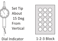
Use a dial indicator and 1−2−3 block to find and set the fixture offset Z.
Load CNC Program
Download the CNC program from your computer to the machine control using RS−232 communications, USB flash memory, or floppy disk.
Run Program
Run the program, using extra caution until the program is proven to be error−free.
Adjust Offsets as Required
Check the part features and adjust the CDC or TLO registers as needed to ensure the part is within design specifications.
Shut Down
Remove tools from the spindle, clean the work area, and properly shut down the machine. Be sure to clean the work area and leave the machine and tools in the location and condition you found them.
Warning
Never operate a CNC machine or any shop equipment unless you have been properly trained on its use. Observe extreme caution at all times. Follow all safety rules.
6.2 Machine and Tool Offsets
Fixture Offset XY
Figure 2 shows a plan view of how the Fixture Offset XY works. The CNC operator finds the fixture offset values by jogging (moving) the machine from the machine at its home position the CNC program datum. This can be any point on the part, stock, or fixture, as long as it can be found by mechanical means such as an edge finder or part probe.
جهت خرید قطعات سی ان سی و اطلاع از قیمت های لوازم cnc اینجا کلیک کنید.
The incremental X and Y distances moved between points is recorded and entered into a Fixture Offset Register on the CNC control. Think of the Offset registers like a table in a spreadsheet. The CNC control references these values in the table each time a motion is commanded, adding or subtracting them from coordinates in the CNC program. In other words, Fixture XY offsets convert Machine Coordinates into WCS coordinates.
Most machine controls support at least six fixture offsets, labeled G54 thru G59. Multiple registers are needed because most parts use a different fixture offset for each side of the part machined.
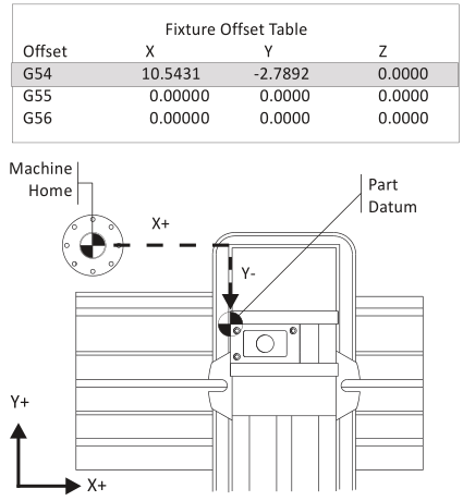
Figure 3: Fixture Offset Plan View
The Fixture Offset Z−coordinate is not used to shift the Machine Z. Use of the Fixture Offset Z is covered in the next topic.
Fixture Offset Z
The purpose of the Fixture Offset Z is to record the incremental distance from a tool setting position to the part datum. The tool set position can be a tool probe or, as shown in Figure 10, the top of a precision 1−2−3 block set on the machine table. The approach shown in Figure 10 involves using a dial indicator and this process is detailed in Lesson 6 (CNC Operation: Set Fixture Offset Z).
The CNC control adds the Fixture Offset Z and Tool Length Offset for the active tool together to calculate the distance from the tip of each tool at Home to the Z−datum on the part.
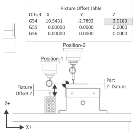
Figure 10: Fixture Offset Z
Tool Length Offset (TLO)
Every tool loaded into the machine is a different length. In fact, if a tool is replaced due to wear or breaking, the length of its replacement will likely change because it is almost impossible to set a new tool in the holder in exactly the same place as the old one. The CNC machine needs some way of knowing how far each tool extends from the spindle to the tip. This is accomplished using a Tool Length Offset (TLO).
The TLO is found by jogging the spindle with tool from the machine home Z−position to the tool setting point on the machine. This can be the top of a tool probe, or as shown in Figure 11, the top of a 1−2−3 block resting on the machine table. The distance travelled from home to the top of the block is recorded, and the value entered into the TLO register for that tool (called an H−register, because it is preceded by the letter H in the CNC program).
If a tool wears or breaks, it can be replaced, the H−register reset to the new tool by touching off again on the 1−2−3 block, and the program continued with no other changes.

Figure 11: Tool Length Offset
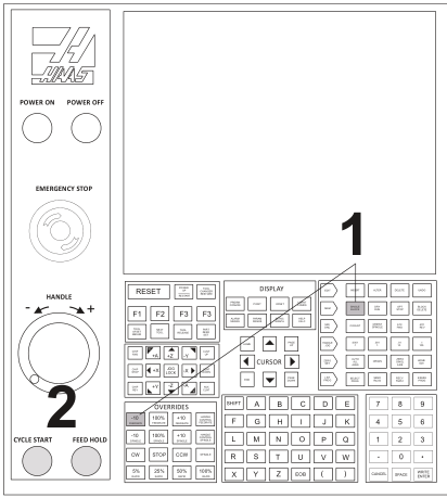
Haas Control
The Haas control is shown in Figures 2 and 3. Familiarize yourself with the location of buttons and controls. Detailed instructions on the following pages show how to operate the control.
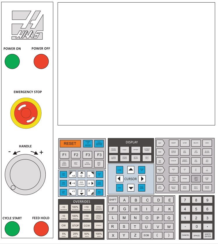
Figure 2: Haas CNC Mill Control
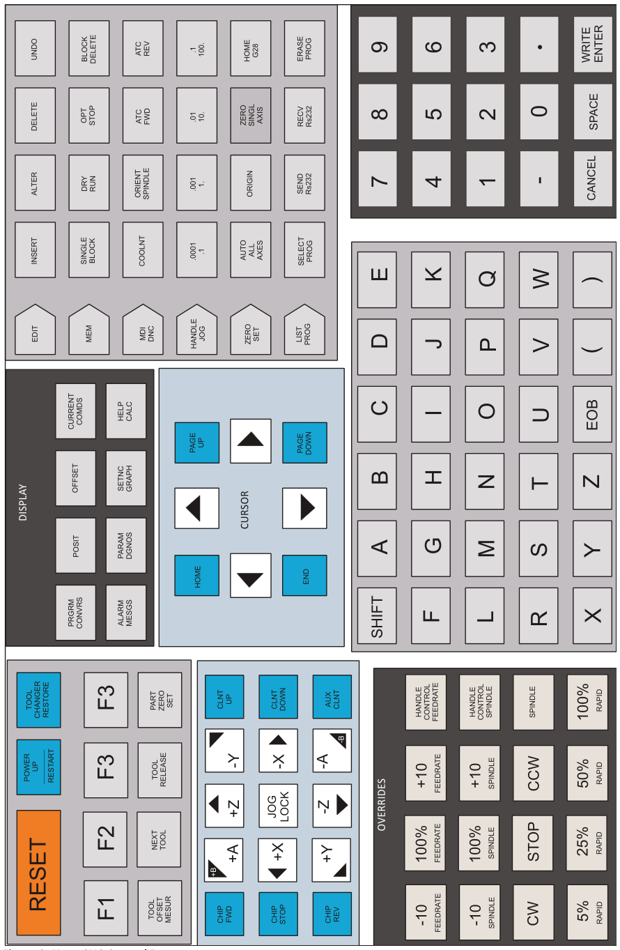
Figure 3: Haas CNC Control Buttons
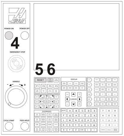
Start/Home Machine
|
Check List |
Buttons |
|
|
1 |
Work Area: Clear |
|
|
2 |
Air Supply: OnƒCorrect Haas requires at least 70PSI for tool changer to operate. |
|
|
3 |
Main Breaker: On |
|
|
4 |
POWER ON: Press
|
 |
|
5 |
RESET: Press |
 |
|
6 |
Power On Restart: Press
|
 |
 |
||
Load Tools
|
Check List |
Buttons |
|
|
1 |
MDI/DNC Key: Select |
 |
|
2 |
Tool Number: Enter
|
 |
|
3 |
ATC FWD: Select Tool carousel will position. |
 |
|
|
||
|
4 |
Position Tool in Spindle
Ensure “dogs” on spindle line up with slots on tool holder. |
 |
|
5 |
Tool Release: Select
|
 |
|
6 |
Repeat Repeat steps 2−5 until all tools are loaded. |
|
|
|
||


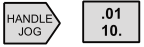
Set Tool Length Offset (TLO)
|
1 |
Handle Jog Mode: Select This sets machine to be controlled by the hand wheel. |
 |
|
2 |
Jog Increment: .01 This sets the job increment so each click of the hand wheel moves the tool .01 inches in the jog direction. |
 |
|
3 |
Jog Direction: Z This sets the tool to move in Z when the jog handle is moved. |
 |
|
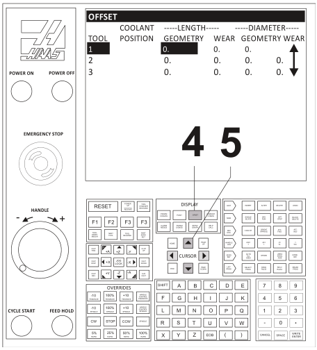
Note: Machine parameter 64 (T OFS MEAS USES WORK) must be set to OFF to use this method.
|
||
|
4 |
Offsets: Select Press this button until the Tool Offset page displays. |
 |
|
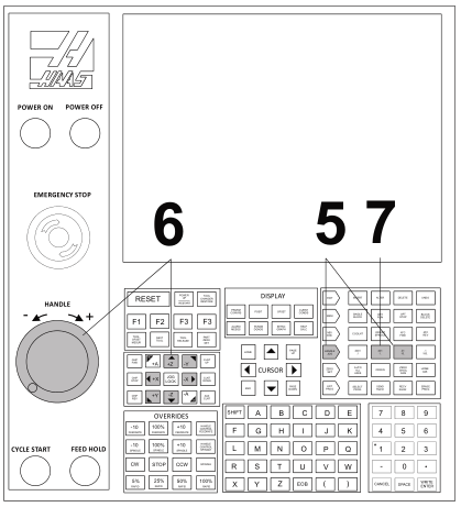
5 |
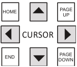
Cursor Arrows: Align for active tool Use the Up−Dn cursor keys (if needed) to move the highlighted bar on the graphics display over the offset values for the currently active tool. |
 |
 |
||
|
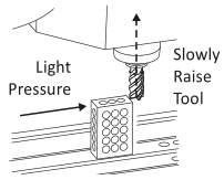
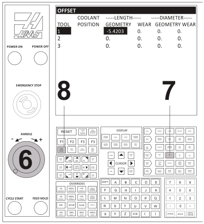
6 |
Use 1-2-3 Block to Set Tool Length
|
 |
|
7 |
Jog Increment: .001 Reduce jog increment and use jog handle to raise tool in .001 increments until it just slides under the block again. |
 |
|
8 |
Tool Offset Measure: Select
|
 |
|
|
||
|
9 |
Next Tool: Select
|
 |
|
|
||

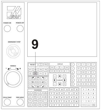
ips
- Do not press any buttons between steps 8−9 or NEXT TOOL button will not load next
- If you should press any buttons and interrupt this process, load the next tool by selecting the ATC FWD button, followed by HANDLE JOG.
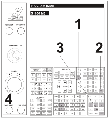
Set Fixture Offset XY
|
1 |
MDI/DNC Key: Select Erase Prog: Select commands) |
 |
|
2 |
Erase Prog: Select commands) |
 |
|
3 |
Spindle Speed: S1100
|
 |
|
4 |
Cycle Start: Select Spindle will start CW at 1100 RPM |
 |
 |
||
|
5 |
Handle Jog: Select Jog Increment: .01 |
 |
|
6 |
Jog Handle: As Needed Select jog direction and use handle as required to place edge finder stylus alongside the left part edge. |
 |
|
7 |
Jog Increment: .001
|
 |
 |
||
 |
||
|
8 |
Jog Handle: Retract in Z Jog straight upward in Z until edge finder is above part and jog handle reads zero on the dial. |
 |
|
9 |
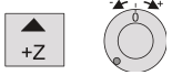
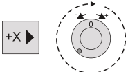
Jog Handle: Set jog direction to +X and rotate handle one full turn clockwise. Since the control is in .001 increment mode, rotating the dial exactly one full turn places the center of the spindle directly over the left part edge. |
 |
|
10 |
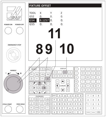
Offset Page: Select Select Offset button and PgUpƒPgDn buttons until Work Zero Offset page appears. Use Arrow keys to highlight G54 (or whatever fixture offset is to be set). |
 |
|
11 |
Part Zero Set: Select This sets the G54 X value to the current spindle position. |
 |
 |
||
|
Tips
|
||
|
The following instructions repeat steps 4-10 but for setting the Y-axis. |
||
|
12 |
Jog Handle: As Needed
|
 |
|
13 |
Jog Increment: .001
exactly .100 from the part edge. |
 |
|
14 |
Jog Handle: Retract in Z
|
 |
|
15 |
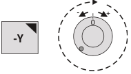
Jog Handle: Set jog direction to −Y and rotate handle one full turn clockwise.
|
 |
|
16 |
Offset Page: Use arrow keys to highlight G54 field (or whichever fixture offset you are setting). |
 |
|
17 |
Part Zero Set: Select This sets the G54 Y value to the current spindle position. |
 |
|
18 |
Spindle Stop: Select |
|
Set Fixture Offset Z
|
Check List |
Buttons |
||
|
1 |
Prepare:
|
 |
|
|
2 |
MDI Mode: Select
|
 |
|
|
3 |
Handle: As Needed
|
 |
|
 |
|||
|
Note: Machine parameter 64 (T OFS MEAS USES WORK) must be set to OFF to use this method. |
|||
|
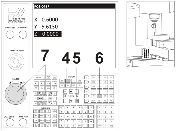
4 |
Posit Button: Press |
 |
|
|
5 |
Operator Screen: Select Use PG DN Button (5 times) until POS−OPER screen appears. |
 |
|
|
6 |
Origin: Set Press Origin button to set Z−value on operator screen to zero. |
 |
|
|
7 |
Handle: As Needed Select jog direction and use handle as required to place dial indicator stylus on top of part stock and the dial reads zero. |
 |
|
 |
|||
|
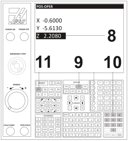
8 |
Operator Z Value: Read
|
|
|
|
9 |
Offset Page: Set G54 Z Value
|
 |
|
|
10 |
Numeric Keypad: Enter Z Value
|
 |
|
|
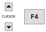
11 |
F1 Button: Press
|
 |
|
 |
|||
|
Tip Shift the datum DOWN by an incremental distance from the top of the part to remove stock from the top−face by subtracting the amount of stock to remove from the Fixture Offset Z Value. |
Example: To set the datum to Z−.02 below the top of the part: 2.2080Z 0.020- 2.1880- |
||
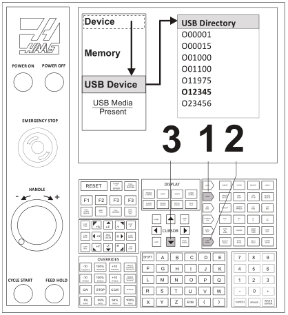
Load CNC Program
|
لیست بررسی |
دکمهها |
|
|
1 |
Memory: Select |
 |
|
2 |
List Programs: Select |
 |
|
3 |
USB Device: Select
|
 |
 |
||
|
4 |
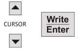
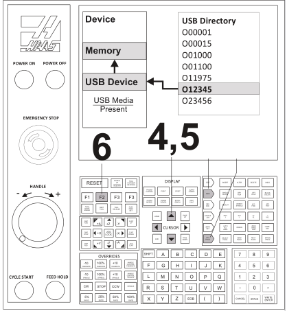
Program Name: Highlight
|
 |
|
5 |
Write To Device (Memory): Select Press the Left arrow key and then the Up arrow key to move the highlight bar back over the Memory option in the Device list. |
 |
|
6 |
F2: Select
|
 |
 |
||
|
Note: All programs must begin with the letter “O” (NOT the number zero). The program name must be an integer up to five digits long. No decimal point, letters, or special characters are allowed. |
||
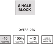
Run CNC Program
This is the preferred process for running a new program. Once a program is proven, all feed rates can be set to 100% and single block mode can be set to off.
|
لیست بررسی |
دکمهها |
|
|
1 |
Pre-Start
|
 |
|
2 |
Start
|
 |
 |
||
Caution: A common error is setting the Fixture or Tool Length offset incorrectly. When running a program for the first time, set the machine to Single block mode. Reduce rapid feed rate to 25%, and proceed with caution. Once the tool is cutting, turn off single block mode and let the program run. Do not leave the machine unattended, and keep one hand on the feed hold button. Listen, watch chip formation, and be ready to adjust cutting feed rates to suite cutting conditions.
جهت خرید قطعات سی ان سی و اطلاع از قیمت های لوازم cnc اینجا کلیک کنید.
Adjusting CDC Offsets
|
Machining operations that use Cutter Diameter Compensation (CDC: G41/G42) can be adjusted to account for tool wear and deflection. Measure across a finished feature on part and compare it with the desired value. Subtract the Actual from the Target sizes and enter the difference into the CDC register on the control for that tool. For example: Target Feature Size: 1.0000 Actual Feature Size: 1.0120 Wear Value: -0.0120 The tool path will now be compensated for the size difference. Running the same operation again should result in the feature being exactly the target size. |
||
|
Wear compensation is used only on contour passes. It is not used for face milling, 3D milling, or drill cycles. Select the Wear Compensation option in your CAD/CAM software and, if needed, set a Tool Diameter Wear value as shown above. When used, the wear value is always a negative number. Always set Tool Diameter Geometry to zero for all tools since CAD/CAM software already accounts for the tool diameter by programming the tool center line path. |
||
|
Check List |
Buttons |
|
|
1 |
Offset Page: Select |
 |
|
2 |
Adjust Diameter Offset
|
 |
 |
||
Shut Down CNC
|
Check List |
Buttons | |
|
1 |
Remove tool from spindle:
|
 |
|
2 |
Jog Machine to Safe Area:
|
|
|
3 |
Shut Down Button: Press |
 |
|
Post Power-Down Checklist:
|
||
Note: It is important to clean the machine after each use to prevent corrosion, promote a safe work environment, and as a professional courtesy to others. Allow at least 15−30 minutes at the end of each day for cleaning. At the very least, put away all unused tools and tooling, wash down the machine with coolant, remove standing coolant from the table, and run the chip conveyor.